archive(Projects)
Projection dome
Ever since my first hands on a computer in the eighties, my dream has been to have a room as described in Ray Bradbury's short story 'The Veldt'. A virtual reality room to explore.
Technology is now getting close to this dream (if we ignore the psychological element to the story).
This is a project to enable me to immerse myself completely in the mmporgs I play (Eve-online, TESO, ....) and maybe also to explore virtual landscapes, museums etc as envisaged by Ray Bradbury.
I have started this project several times all with no success until recently (I am not very manual), I found a link that described the simplest method for constructing a dome. This is my attempt number 4 :)
First off, here are some useful links to explain the basis of the project :
My initial attempts were based on trying to get a real spherical dome (hence the failures). I then decided to go for the geodesic dome and there are plenty of sites enabling one to calculate the dimensions of a geodesic dome. This is one that I used :


Technology is now getting close to this dream (if we ignore the psychological element to the story).
This is a project to enable me to immerse myself completely in the mmporgs I play (Eve-online, TESO, ....) and maybe also to explore virtual landscapes, museums etc as envisaged by Ray Bradbury.
I have started this project several times all with no success until recently (I am not very manual), I found a link that described the simplest method for constructing a dome. This is my attempt number 4 :)
First off, here are some useful links to explain the basis of the project :
This link gives the principal idea behind the project; replacing the expensive lens systems for spherical projection used by planetariums and tourist centers like Futuroscope in Poitiers, France (by the way, if you haven't been there, I highly recommend it):
My initial attempts were based on trying to get a real spherical dome (hence the failures). I then decided to go for the geodesic dome and there are plenty of sites enabling one to calculate the dimensions of a geodesic dome. This is one that I used :
The link is for a 3V geodesic dome which I feel is a good compromise between the number of triangles and the 'dome smoothness' for projection. For a 2 metre diametre dome this means 75 triangles to cut (2 types of triangles).
For the triangles I obtained cardboard boxes (the type used for moving house). The dimensions have to be farely big. I found it easier to buy them than trying to get enough for 75 triangles. I bought them at my local Leclerc Brico at 2.99€ each.
Each box was 80 * 40 *40cm which gave me 4 Type A triangles per box or 6 * Type B triangles per box. Unfortunately lots of waste but can't be helped if you avoid the creases that are used to create the box.
Résumé of the materials and costs :
- 17 Packing boxes (80 * 40 * 40cm) €51
- 3 White glue (example : Giotto BIB Bricolage) €25
- A good metal cutting ruler €10
- A good stanley knife €5
- 2 plastics 5mm sheets (50 * 40cm approx) €10
(costs are approximate).
I avoided the simple 30cm metal rulers as there is a lot of cutting involved, I opted for a heavy duty ruler with handle as is the case with the stanley knife. No sense risking injury.
First stage
So, according to the geodesic dome calculator, we have 45 triangles (40cm base with 41cm sides) and 30 triangles (40cm base with 35cm sides). Each triangle has to have 2cm flaps on each side so that they can be glued together

First thing is cut these two triangles with their flaps on the plastic sheets. These plastics sheets will be our templates for the cardboard cutting (saves time measuring).
40/35/35 triangle plastic template

40/41/41 triangle plastic template
Once the models are cut and ready then we can start drawing the flapped triangles on the cardboard. As I said one can get 4 type As and 6 type Bs :
Type A cut plan (one side of the box being shown ):


Template with one triangle drawn
Type B cut plan (one side of the box being shown and obviously not to scale ):

The drawing is naff but the last triangle I had to mirror turn to fit in. There is a possible configuration that one can find using the mask to fit 6 triangles per packing box for the type Bs.

One template and folded cardboard triangle
Once all the triangles were cut then I modified the plastic templates. I removed the flaps from each triangle (only on the plastic sheet templates!). Now with two new templates fot the exact triangle sizes, I could now draw the triangles on each of the 75 cardboard flapped triangles.
This meant I then I had a guide for folding the flaps. I used the heavy duty metal ruler to provide a clean fold along each flap.
Second stage
Second stage involved gluing all these traingles together. According to the Geodesic calculator site it seems that the dome is composed on a second level of hexagons and pentagons (actually they opt for the larger triangle : hexagon with 3 smaller triangles at each corner but I figured this would be impractical).
So I set to produce 5 hexagons, 5 half hexagons using the 40/41/41 triangles and 6 pentagons using the 41/35/35 triangles.

Pentagons, hexagons and half hexagons
3rd stage
3rd stage involved painting the shapes. I chose a very very light grey. Most projection surfaces use an almost 15% grey and knowing that I will be losing a lot of light during the various process getting the image to the screen, I opted for an almost white grey. In the hope that this will still reduce interior reflected light and still permit a bright projected image. I estimate that its a 5% grey.
I opted to do the painting now so that I can cover the joins with masking tape and hopefully reduce the unwanted bumps and crevices of all the triangles. This would be easier before completing the dome.

Painted pentagon
To be continued......
Dobson
Projet de construction d'un téléscope dobson
En 2008 j'ai commencé un projet de création d'un téléscope dobson avec comme premier étape la création du mirroir de 250 mm
Après plusieurs semaines d'investigation, de recherches et lecture je me suis lancé en commandant le verre pyrex de 10" et un kit de polissage auprès de GotGrit
Pendant mes recherches j'ai trouvé sur le site stellafane la suite des abrasives recommandés (en microns):
420
254
165
102
63
32
20
15
12
9
5

254
165
102
63
32
20
15
12
9
5
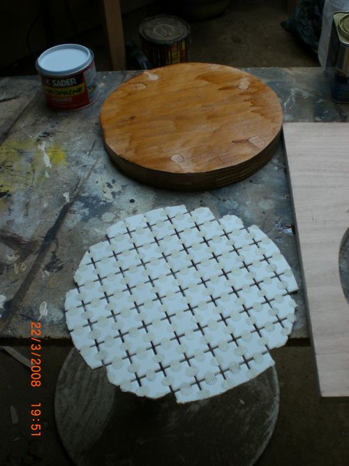
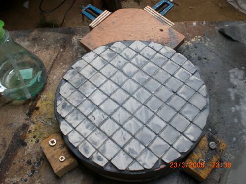
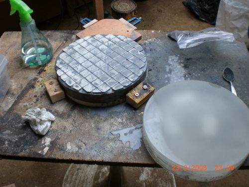
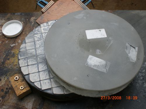
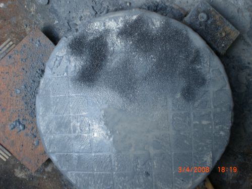
1. Construction de l'outil pour rendre le verre sphérique

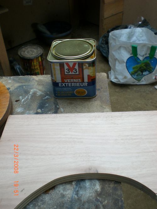
Le verni utilisé pour la base de l'outil en bois
Suivi de l'étape de polissage avec Cerium Oxide et l'outil poix.
Cet étape terminé en fin 2008 avec un constat : des rayures très fines sur la surface du mirroir (probablement dû à l'environement non propre et donc quelques grains d'abrasives d'une phase précedent).
J'ai aussi construit un banc de test d'optique en utilisant le plan fourni sur ce site :
(Pour info: Détail des étapes notés en 2008 et repris ici en 2012. Donc il peut y avoir des erreurs de lecture/mémoire).


